 |
 |
|
 |
AZURAHORN |
|---|
Le Cléac’h Acoustic Horns |
|---|
| Homepage |
| Horns |
| Trade Secrets |
| Gallery |
| Ordering & Shipping |
| Links |
| Trade Secrets | |||||||||||||||||||||||||||||||||||||||||||||||||||||||||||||||
For anyone contemplating their own acoustic horn factory........ |
|||||||||||||||||||||||||||||||||||||||||||||||||||||||||||||||
 |
 |
|---|
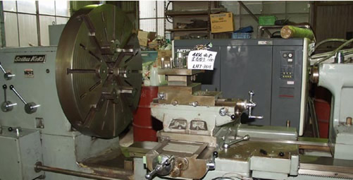
Here is the azura machine – a round table on a 1” shaft driven by a Woodlathe and skateboard wheel.
 |
 |
|---|---|
Cutting the profile
 |
My eureka moment: Jig up a 100mm angle grinder on a plate like this … |
|---|
The angle grinder has the template follower concentric with the cutting wheel – this means the cut is not effected by the angle the grinder is held at relative to the work. This has the enormous advantage of enabling the curve to be ground exactly to the template – not hand finished to match it. There’s a big difference.
Template
The Template is made from 6mm MDF. Mount steel ruler as shown and ensure the set square runs smoothly up and down. Plot the curve from x,y coordinates. like this ….
 |
 |
|---|
The cutting tool fulcrum must however follow a curve equidistant from the desired curve. This curve is achieved by the simple expedient of describing multiple arcs back from the desired curve. The equation defeated me – but that’s what geometry is for. Offset is half the grinder wheel diameter - PLUS half the bearing diameter.
Update: Jean-Michel kindly designed me a curve calculator spreadsheet with the equidistant curve delineated. All that is now needed is to plot this onto the mdf sheet. |
|||
|---|---|---|---|
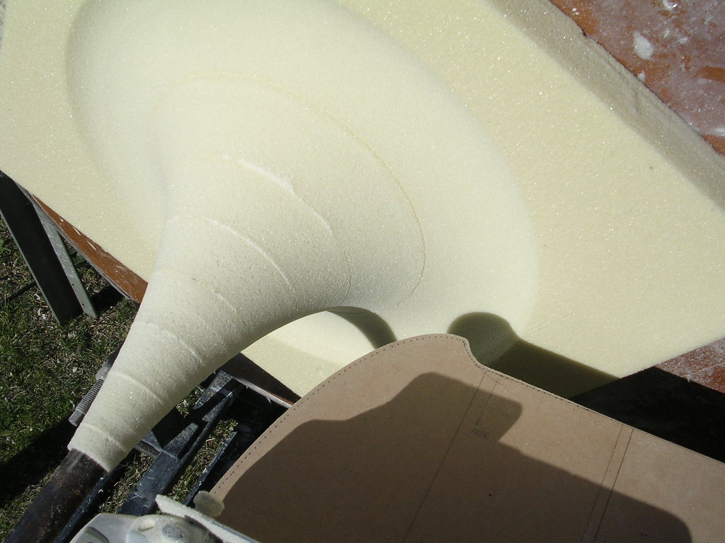
Making a plug mould
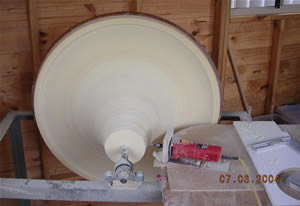 |
The plug mould blank is made from polyurethane foam – built up in layers from sheet, or 2-pack poured into a rough mould. The initial shape is turned from this blank with the grinder, a few mm short of the final curve. Next, a fibreglass layer is built up on this, and ground to just shy of the final curve. The last layer is gel coat, or an easy sanding primer, ground to the finished profile. Remove the grinder marks by light hand fairing, and polish. The trick is to sand back the template in stages until achieving the final curve at the last pass. The finished plug mould is only used once. The first female is taken off and further finishing is done on this. From this female the production mould is made.
|
|---|---|
 |
 |
Laying up
Polish mould with releasing wax
Gel coat 1
Gel coat 2 – make thicker round the throat area
Resin / matting 1
Resin / matting 2
Resin / matting 3
Flowcoat / Q-cell mix
Flowcoat
Break out product from mould – 3mm mdf wedges works best
Trim off edges and sand back to top of step
Finishing
Images are self explanatory…
Cut throats - jigged up angle grinder and adjustable bench
Ream to exact size with tapered sanding reamer
Cast the flange – mix resin and calc carb.
Mark up and drill driver mounting holes
Update: brass template for drilling flanges - most accurate method of drilling the mounting holes.
Surface finish
Update: spinner for surface finishing made from cheap Bunnings wood lathe with lay shaft and trusty skateboard wheel…
Cutting throats
 |
 |
|---|---|
 |
 |
 |
||
|---|---|---|---|
 |
|||
 |
 |
||
|---|---|---|---|
 |
 |
 |
|
|---|---|---|---|
 |
 |
 |
 |
 |
 |
|
|---|---|---|---|
|
|
|---|---|


